NIF addresses the universal RT instability all implosion fusion schemes must face, is there 7more that they can do?
NIF people limited the impact of the RT instability in their most recent report. But they have more to do and surprises to absorb before they achieve their goals. This is our 4th post in this thread. Summary of our previous 3:
- Gain: Target implosions produced about as much energy as was applied.
- Enhanced heating: The fusion reaction is starting to cause more fusion. First step towards an ignited plasma core.
- Not in-control: The stagnation core at the end of the implosion is an inefficient donut with hard peanuts on one side, should be a plum with a hard/hot central core.
- Something is not working as expected: Are there hidden issues that block success?
This is a “popular” discussion, not a truly technical one, but we must estimate one more technical topic if we want to understand. But you may skip the close-up discussion; click Summary and jump past the nitty-gritty details.
Click any image to expand to full size.
Rayleigh-Taylor Instabilities

Fig 1 RT mixing of water
The RT (Rayleigh-Taylor) instability is the hard reality that ICF researchers must accommodate. When a heavy liquid pushes on a lighter one, RT mixes the boundary with growing turbulence.
Fig 1 shows the beginnings of RT driven tendrils from the red (heavier) water into the lighter, clear water.
Click the here to see the full discussion of this effect.
RT is a universal instability
It is insidiousness because any bump, no matter how small, will grow and never stop growing.

Fig 3 Simulated collapse of a target due to bumps on the target surface
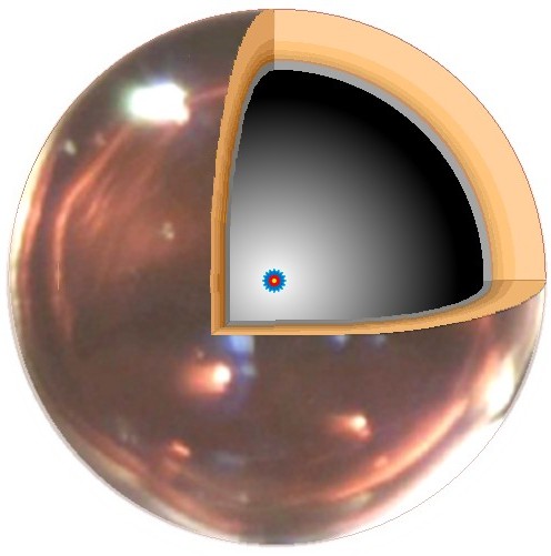
Fig 2 Target cutaway
Fig 2 is the target design (from our previous post). Click this link to see the Specification Table.
Fig 3 shows a computer model of an imploding ICF target, driven by non uniform bams; this was done at LLNL and displays the RT turbulent structures. Top half of the target is shown. The structure causes havoc when the fuel compresses into its stagnation-point core.
RT starts with very small bumps on the interface. In Fig 3, the largest tendrils are from the fuel penetrating into the low pressure in the cavity. The bumps expand exponentially, driven by RT mixing caused by the monstrous drive acceleration not Earth gravity.
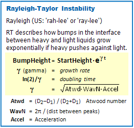
Tbl A Formulas to calculate RT effects – simplest model
Now the math: The answer to:
Will RT appear? … is always YES, whenever a dense fluid pushes against a lighter one.
The correct question is:
WHEN will RT effects start to mess things up? … this has to be estimated.
Table A defines our terms. A target has two interfaces that can generate RT instabilities, • the Shell Wall to Fuel surface and the • Fuel to inner cavity surface
StartHeight is the size of the initial bump. The smaller the bump the longer it takes to be noticed, but bumps will grow like penny stacks discussed in the “exponentially” link, above.
BumpHeight is the size a time t after the beams have turned on.
Gamma The rate of growth of a bump in the interface. It determines how fast the bump will rise, the bigger gamma, the faster the growth, the sooner RT turbulence becomes an issue.
Doubling Time A bump doubles in size every time the clock ticks through It will be easier to understand and most calculators with the [Log] key has the [Ln] key too.
Estimating Gamma means we have to estimate 3 quantities
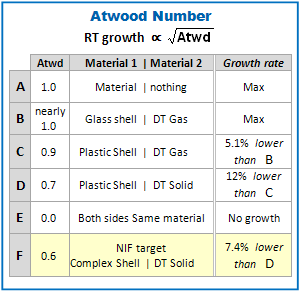
Tbl B Atwood values for target shells
Atwd is the Atwood number. It is the difference between the two densities of the 2 materials divided by their sum. Table B gives some values for this function.
Case A applies for the inner surface of the fuel cell, solid DT on one side, essentially nothing in the cavity. Cases B, C, D, and F refer to the interface between the pusher shell and the solid fuel.
Case F is for the shell/fuel interface in the current NIF target. The value Atwd=0.5 for F instead of 0.6 would make the RT growth rate 15.5% lower than D, a simple PVA plastic shell with a cryo fuel layer. The 0.5 might justify the much larger target expense, but we will stay with the conservative 0.6 guess in F.
KMS built the shells used by most ICF labs in the 1970s and ’80s, Here is my link for the our simple estimates.
 WavN is the Wave Number, units of “per cm.” Basically, 2π divided by the average distance between successive RT peaks. This assumes number of peaks is 10. If it were actually 8 or 12, the square root in the growth rate would change the effects only a bit.
Accel was discussed in the Target Demands table (post -3, this thread),
and is 7.2×10¹² m/s2. This enters the RT growth rate as its square root, too.

Tbl C RT Instability growth, Summary
Table C shows that, at both boundaries (Shell|Fuel and Fuel|Cavity), any and all imperfections grow by a factor of 5 or 6. This means the Target Fabricators must keep all surface bumps below some maximum size, or the targets will fail to meet goals for high efficiency; the shell will mix and “poison” the fuel, or the fuel will not converge into a spherical core.
Same argument goes for the drive beams; they must all turn on at the same time so that implosion irregularity does not locally cause (much) worse RT effects. Of course, beams that are hugely out of balance will destroy the collapse without any help from RT. This was the topic of the last post where we pointed out ICF labs have been serving up donuts for decades.

Tbl D RT limits to flaw sizes
Table D is our bottom line to Rayleigh-Taylor effects on ICF implosions. Recall that the target is 2.2 mm id diameter (about 1/8 of an inch). The fuel layer is 70 microns thick (slightly thinner than writing paper)
The Shell | Fuel irregularity limit is on the ID of the tiny plastic sphere and are about 0.1 % of the shell thickness. the Fuel | Cavity limits represent about 0.1% of the Fuel layer, too.
These requirements cannot be met.
What NIF Reports Mean
The NIF data are a single start of the unfolding of ICF capabilities, not the final results. We will see much better one before they have finished. … but lets evaluate current status
Seven requirements for fusion success
Target Criteria
- Fuel: Cryogenic solid layer, vacuum cavity – Best bang-time convergence (highest density, reduced Atwood number – next point)
- Shell: Lowest element mass, Z – Minimize the Atwood number and minimize Rayleigh-Taylor instability of a high mass pusher driving a much lighter fuel layer.
- Shell: Symmetric as possible – Avoid instabilities that shred the implosion, mix fuel and shell material. Use perfect spheres (conic eccentricity= 0), perfect surface finish (RMS = 0).
Drive Beam Criteria
- Wavelength – make as short as feasible. Minimize fuel preheat (which blocks compression), avoid excessive loss of beam power to the ablating plasma.
- Pulse Shape Control – control shocks on ablating shell, initial preheat of fuel, then gentle ramp-up of the drive with a hard push at stagnation. Follow adiabat ( min entropy trajectory) through the implosion phase space
- Symmetry: Spatial – Avoid hot spots that drive instabilities. Every beam with uniform intensity, all beams with same intensity.
- Symmetry: Temporal – Avoid time dependent hot spots or regions that implode faster or slower than average.
Items 1-3, NIF does these well, as best as can be accomplished.
Item 4, put a check next to this, too, because of the indirect-drive x-ray strategy. The conversion from IR to X-ray is lossy, but at least it is in place at high power. But a UV laser like a KrF system would be much more efficient.
Item 5, a work in progress, not done yet – the laser appears to have all the control capabilities desired. But as we discuss, optimal strategy is still under development.
Item 6 is not under control, as evidenced by the poor shape of the collapsed core. This will never be perfect because each of the 192 beams have spatial hot spots, though uncontrolled, unsmooth beams were expected to be smoothed hohlraum. The inner layer of solid DT fuel will self-smooth by what its discoverers called Beta Heating.
Item 7 was never meant to be controlled (IMHO). The 192 separate beamlines turn on not quite together (guess: within slightly less than 1 ns. ) I suspect beam space and time inequalities were meant to be smoothed by the x-ray conversion.
Non uniformity may be why they use a helium prefill of the hohlraum. Edwards made a comment to this effect in his report (last post). However, there may be jetting from the gold and this would mess up expected smoothing. If true, it would add to my arguments against excessive trust in simulations, even when done by the LLNL theory powerhouse.
Beam irregularities and RT have messed up many a target shot.

Fig 4 Square pulse, KMS 1985-86 data
Our simple estimates on the effects of RT make the IFE (fusion energy generation) task appear impossible. And it is, if one were to use only the square laser pulses as modeled.
Square: beam OFF at start, beam ON at full power during shot, beam OFF at end. [Fig 4, reference.]
The killer assumption is that the stupendous implosive acceleration was fully on at start and constant during the inward drive. Acceleration pushes RT, without it – no RT growth.
Use Fermi degenerate adiabats The idea – dating back to the early days of the 1970s – was to push with a force that kept the electron distribution in their quantum lowest states, the “Fermi degenerate condition.” This is equivalent to saying that we should not push so fast that we increase the entropy of the fuel core, should move system along a thermodynamic adiabat.
Fancy words for “Start with low push (acceleration) and gradually increase the pressure by increasing intensity, until the end.” I am not aware of any actual Fermi-degenerate implosions being done, but this is the prescription for low-RT shots.

Fig 5 Ramped pulse, KMS 1985-86 data
Fig 5, is 30 year old data to show that ramped pulses are nothing new. This is data from the Chroma laser at KMS fusion. The shots are 1/10 the length of NIF shots and the targets were about 1/10 the diameter, too. Chroma was significantly smaller than NIF/10, however.
Ignition and Burn-wave At full run-in, the core will be at its most compacted form, is a plasma, and is way too cold for fusion. Now smack it with the highest power shock to initiate fusion at the center. The products (helium nuclei, “alphas”) will heat up the plasma just outside the core, these heat the next fuel out from the center, and so forth. The ignited, fusion burn wave produces the energy.
Good news: NIF has demonstrated the self heating that means ignition and burn wave is possible! Edward’s Dec 2013 report (see post thread, part 3) indicates that they are working very hard at reduced RT shots.
I am not at all certain I understand the actual shot profile. Edwards’ Report to the NIF Management Advisory Council NMAC) shows Fig 6 as the successful “High Foot” beam profile (pg 17 of the report). “NIC” is the “Low-Foot” profile. The intent seems to be a shock hitting the capsule and causing an inward drift, as the laser beam was held back until the final drive shock of full power at the end.

Fig 7 Park, Hurricane, et al PRL Feb 2014

Fig 6 Edwards High Foot profile Dec 2013
Fig 7 is from the data paper by Park, Hurricane, et al and shows a slightly different “High Foot” success profile. Similar, but there is significant drive power in the plateau between the initial shock and final, power drive shock. These data are in the form or a rough ramp, similar to Fig 5, except …
- the initial preheat shock that starts an inward drift.
- the intermediate power plateau, which does not go away, but continues to gently (?) push the fuel layer inwards.

Fig 8 High Foot with time squared (dotted)
Fig 8 is the High Foot part of Fig 7, to display the shape of the supplied laser power.
The actual success pulses roughly follow the dotted T2 curve drawn over the data.
First the initial preheat shock, then a flat power plateau which starts above the quadratic curve, then goes below it.
What the results would have been if they had followed the T2 profile closer?
Final
The NIF researchers emphasize that they worked hard to reduce the universal RT effects, and the results show that they are on the right path.
- First they shortened the shot duration – is it short enough yet?
- Then they ramped the intensity so that the RT did not rise to destructive levels.
- Next, they plan to try a larger hohlraum to see if they can remove most drive anisotropies.
The NIF workers have done well. I wish them success and hope/expect to see really good results before the end of the year.
………………………………
Charles J. Armentrout, Ann Arbor
2014 Jun 11
Listed under Technology … Technology > ICF/IFE
Have a comment? Click on the title of this post, go to bottom, let us know.
Related posts: Click the INDEX button under the Banner picture
