ITER will begin fusion tests within a decade. We discuss this huge machine.
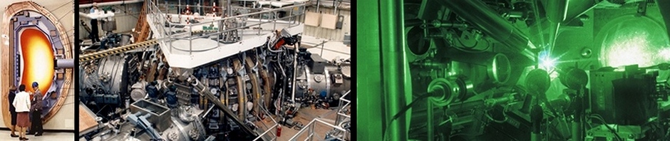
The long awaited fusion test bed, the International Thermonuclear Experimental Reactor, is under construction in Cadarache, France. ITER is an hour (70 km) North of Marseilles (South-Eastern France, not far from the Mediterranean). The facility construction is on-going in France and the machine components are being assembled all around the world.
The ITER team has ambitious goals. This is to be the first magnetic fusion machine to hold a stable plasma for 10 minutes. (They plan to extend operations to 1000 seconds, abut 16 minutes.) The fuel will be deuterium (D) and tritium (T); D is a stable type of hydrogen (H), twice as heavy as H. Fusion techniques are discussed toward the end of Stirring The Pot.
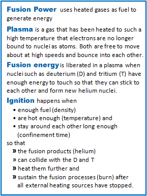
Comment 1 Fusion terms
It will reach fusion temperatures (about 150 M° C … 300 M° F) and ignite. Their goal is to use their ignited plasma to generate 500 MW of output power with a device efficiency of Q = Poutput/Pinput = 10. See Comment 1.
This exceeds the previous record set (1997) at the JET tokamak:
JET: Poutput = 16 MW, Q =0.67 .
This is hotter than any welding torch in any shop anywhere. Hotter than the center of the sun. Good thing, too, since the sun has to last tens of billions of years. If the sun had ITER temperatues, it would last only a small fraction of that.
In this post, we describe the ITER tokamak.
In our next ITER post we will use this discussion to describe a potential design feature that may limit the success of the program, though not until they have tried to reach their goals of fusion temperature; efficiency, Q; and burn times (15-20 years from now).
![]() ITER – Overview
ITER – Overview
ITER, the pronunciation Most people in the business say eat-er. You are allowed to say it anyway you want, just be consistent.
ITER, the acronym The program started up in 1988 as the International Thermonuclear Experimental Reactor. It was an English abbreviation and the central words were thermonuclear and experimental. Although pretty good, the word nuclear had to go.
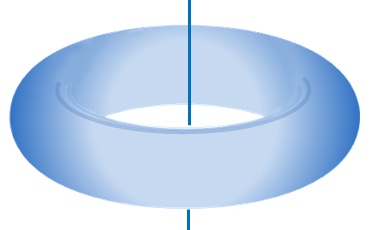
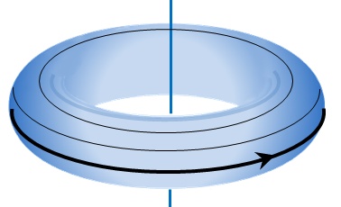
Sketch A Torus – donut shape
- The T stands for thermonuclear and could have been changeable to tokamak; its shape is a torus – Sketch A. (Looks like a bagel, a donut, or a car tire).
- The E is the important part. This machine is truly an experiment to test out ideas, not a prototype for a mass produced product like a car. But… after 120 years of building automobiles, companies that release a new model require thousands of prototype parts and vehicles for destructive testing. Thousands(?) – not going to happen. Definitely not a prototype.
ITER, the history It started in 1988 as a joint venture of 4 countries. The U.S. pulled out maybe a decade ago, then rejoined; nearly withdrew during the Obama days; our DOE just lost significant funding – want to make a bet on our presence 4 years from now? BREXIT may remove the last English speaking country. The countries currently on its guiding council are shown in the logo.
Soon, there might be no English speaking countries left, so disconnect the name from a living language. Voilá – ITER is no longer an acronym! It is okay to write it “Iter,” or “iter.”
ITER is the chosen name because it is dead Latin for The Way.
ITER, the tokamak ITER’s goal is to generate 500 MW of fusion power; support a fusion burn that lasts for 10 minutes (they will try for 1000 seconds, about 16 min); and produce 10 times more power than used by the facility (Q=10). The machine to ultimately perform these is shown in Fig 1. The left side shows its interior lined with its protective first-wall blanket. The right side depicts the blanket being installed.
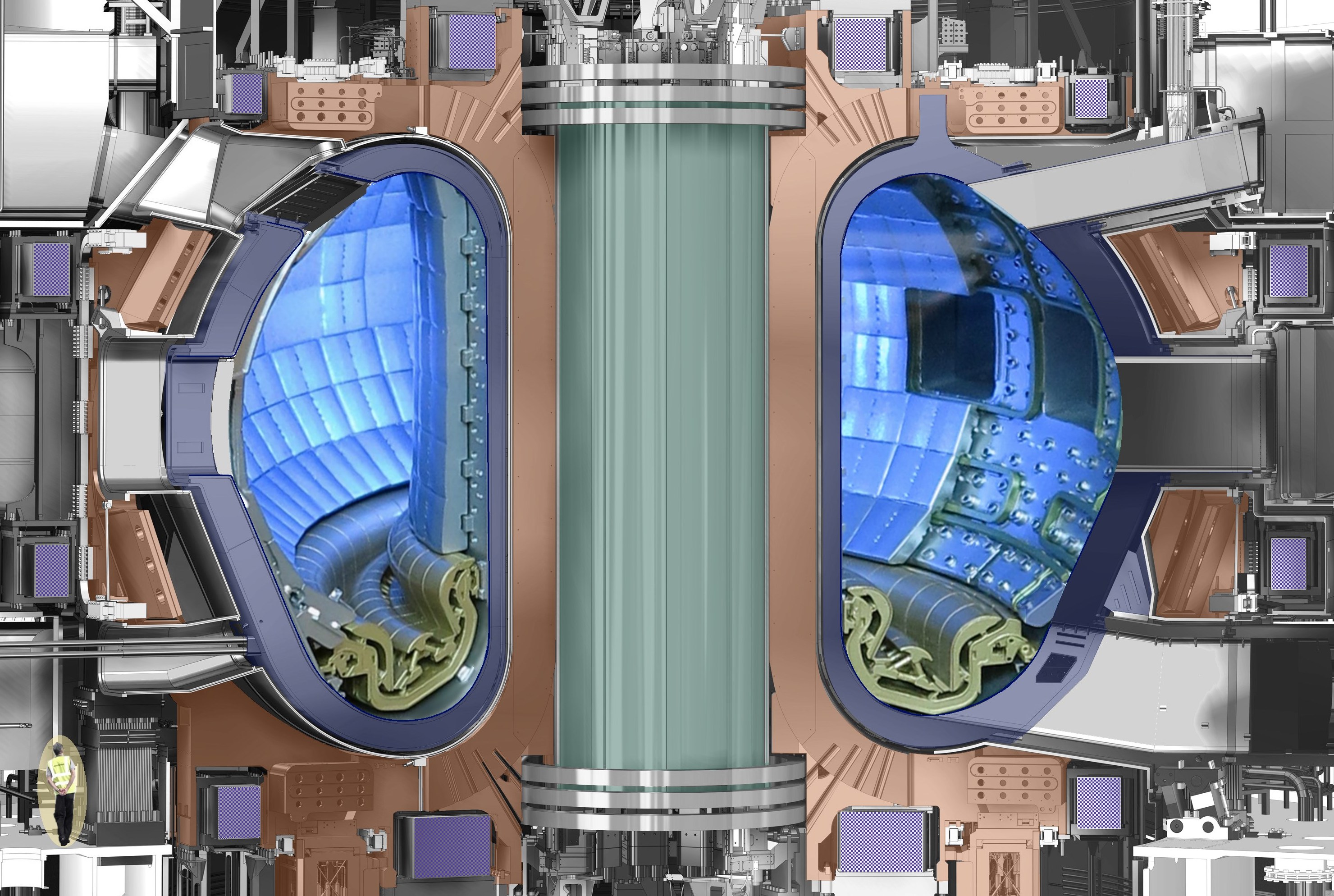
Fig 1 ITER cutaway, man lower left
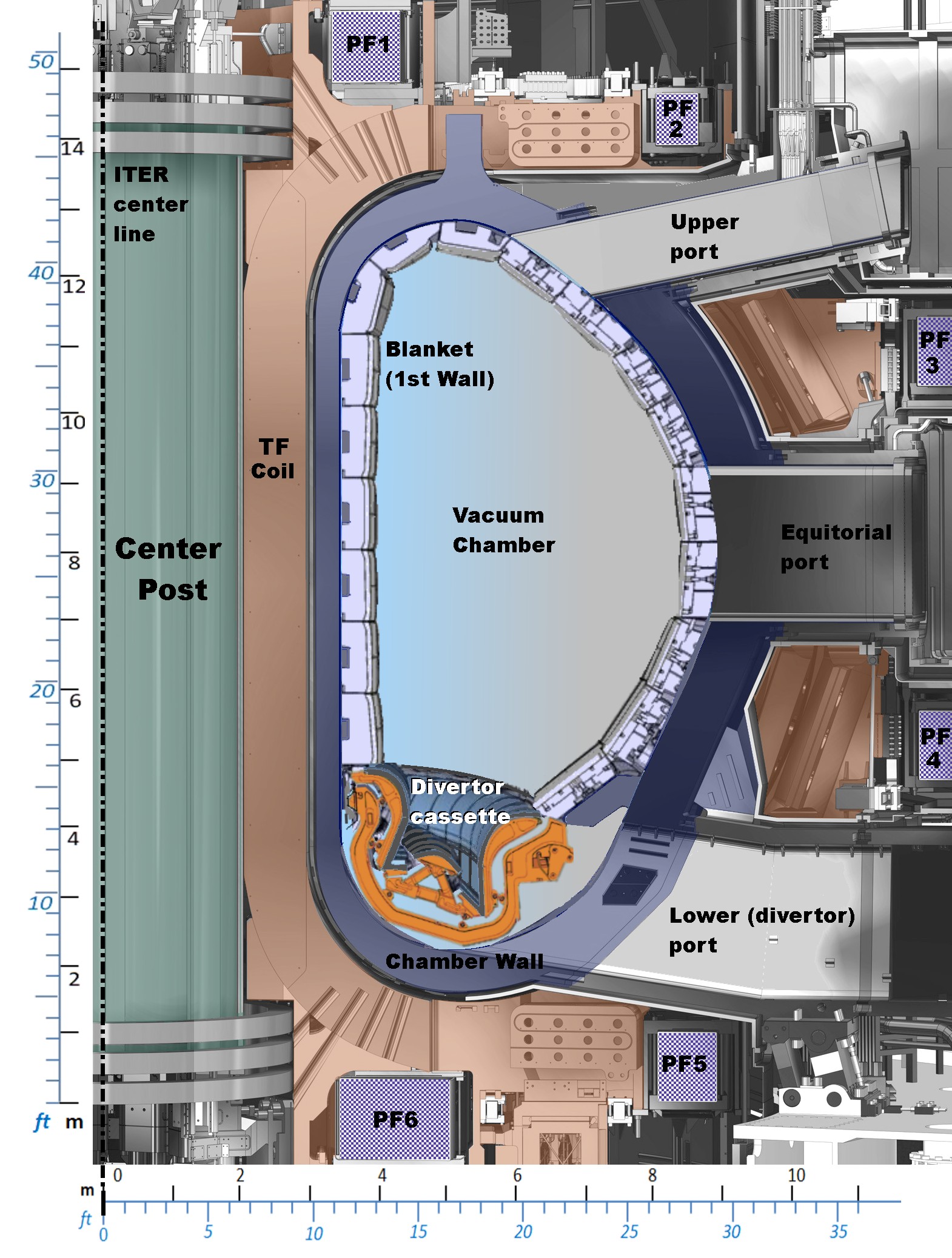
Fig 2 Thin slice through ITER, showing the key features
Click any figure, to see a full sized image. The colors are for identification; unless someone uses a paintbrush, the actual ITER will be metal toned, from dull to shiny gray.
Unless otherwise stated the source of the figures originate with ITER.org. We have modified and colorized most, but the basic drawings for the images are from ITER organization.
Fig 2 is a thin slice out of Fig 1.
Vacuum chamber The chamber is a torus (Sketch A) that wraps about the center post.
Between plasma pulses, the chamber maintains a deeper vacuum than that in Earth orbit. The chamber wall structure holds the cooling lines to keep the walls from melting during each fusion pulse.
A tokamak is a huge, high power transformer. The facility powers the primary coil which drives very high current in the ionized gas “secondary coil” – the plasma.
Sketch B Toroidal direction
The induced current starts heating the plasma to fusion temperatures.
Toroidal field The TF coils (Fig 2) generate a strong magnetic field in the toroidal direction (Sketch B).
Since the current is in a coil is always perpendicular to its generated magnetic field, the toroidal field coils must wrap about the chamber in the poloidal direction (Sketch C).
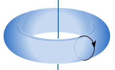
Sketch C Poloidal direction
The TF field is the first part of a tokamak’s confinement strategy.
Poloidal field A poloidal magnetic field loops about the chamber in the direction shown in Sketch C – meaning each of the 6 PF coils form toroidal rings about the center post. These coils shape the plasma to provide a second method for confinement and stability. Note: Tokamak confinement is not the topic for this post.
Center post This prevents the TF coils from twisting due to the magnetic forces. Its outer cover houses the stack of 6 huge ring-shaped primary transformer coils (“center solenoids”) that drive the plasma current necessary for confinement and the initial boost in heating the plasma.
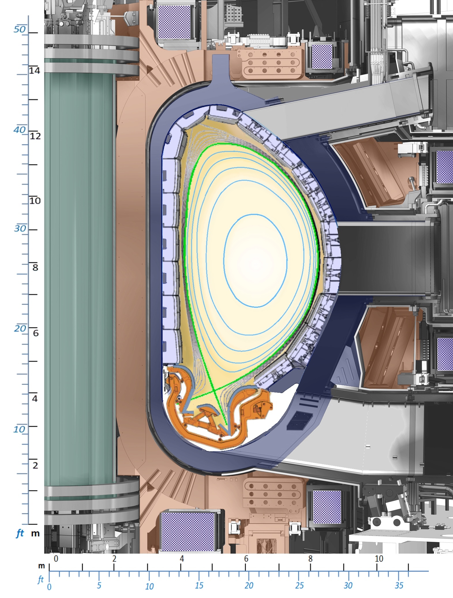
Fig 3 field and plasma ITER with hot plasma and field lines
Fig 3 is similar to Fig 2, but shows the confined fusion-hot plasma.
Inside the hot core, the field lines are not random but lie on closed shells (called flux shells), the nested egg-shaped circles shown. Each magnetic field line is mostly in the toroidal direction, but corkscrews around its flux shell as it moves about the center post.
Since plasma ions and electrons follow a field line, they are confined to the fusion region. Tokamaks became famous when the Russians showed (1968) that this really does work, does confine hot plasma.
The flux shell painted green in Fig 3 (the separatrix) separates the confined central plasma from cooler plasma that runs directly into the wall. Always find the separatrix from its distinctive the × point.
The plasma in the fusing core is at about 150 million degrees C. This is hotter than any welding/cutting torch on Earth, and is actually much hotter than the sun. Without good confinement, the plasma might start to heat up, but could roar through the vacuum walls with unstoppable fury. ITER would destroy itself before it even got started.
Divertor Cartridge Here is what always happens: plasma heats in the confinement region to fusion temperatures and each hot electron and ion will slowly diffuse out of the core until it reaches the separatrix shell.
- Some of this outer plasma diffuses into the chamber walls. The plasma is still fierce enough to erode the first surface. Tests on smaller tokamaks have seen wall materials that have diffused back into central plasma, and poison the fusion reactions. ITER’s first wall is a beryllium alloy, a material that causes minimal plasma poisoning.
- Most of this outermost plasma will rapidly flow directly to the × point where it will flee confinement and will smash into solid material there. Restate – in a fusing plasma, the × point transmits extraordinarily high power onto material walls. This is called the waste heat or waste power issue.

Fig 4 Divertor cassette 3.5m W × 2.3m H
Fig 4 show a divertor cassette that forms the target for the × point exhaust. It is made up of a tungsten (W) alloy on its front “target” surfaces where the plasma strikes.
The divertor cassettes have huge ducts to direct the exhaust into high flow vacuum pumps, and significant cooling through out.
Yet the front surfaces will erode due to the intense plasma attack. The divertors will require frequent replacement.
Why so long a wait?
Dreams of fusion power have been around for a while. Here is the main Fusion Timeline, omitting many things that happened along the way –
1945-1958 The first efforts were highly classified outgrowths of the fusion bomb efforts in both US and in Russia. Fusion power ideas were declassified in 1958
1958-1968 Most labs worked with one of 4 machine types:, mirrors, stellarators, linear pinches and toroidal pinches. None had success lasting longer than microseconds.
1968-1969 Russia published shocking data that its tokamak toroidal pinch actually worked. The U.S. converted its main stellarator into a tokamak and verified Soviet results
1970-now This is the age of the tokamak. In the U.S., most other types lost funding (we commissioned and killed the huge MFTF-B mirror test device
1973 Richard Nixon and Leonard Brezhnev discussed an international cooperation for the very first time, although both countries had active fusion experiment laboratories.
1978-1987 The Nixon/Brezhnev meeting led to the formation of the INTOR (international tokamak reactor) study group. INTOR generated engineering reference diagrams, but no true facility design. In 1981, the U.S. began defunding fusion research in its homeland.
1987 The USA, Euratom, Japan and the USSR signed the ITER collaboration documents. Work started in 1988 on the conceptual design, mostly updates on the INTOR reference design.
2006 The ITER agreement was signed, although it was not actually ratified until 2007, 10 years ago.
2010 ITER facility groundbreaking ceremony (7 years ago).
2015 (December) First machine component delivered.

Comment 2 Meme
If you have only been exposed to the negative meme “Fusion is always 20 years away” choose your time to start. If you chose 1945, why not, instead, 1913, when the Bohr atomic model was developed?
If this had been started in 1981 in just the USA or just Europe, or Japan or Russia it would have been up and running – in half the time and almost certainly at half the price.
Someone referred to a camel as a horse designed by a committee. Well, ITER is a fusion fusion experiment designed by a committee of people from squabbling countries all around the world. The process has also been called wanting a fusion machine in the worst possible way – and doing it that way. Between 1988 and 2010 it was a political game and engineering nightmare, everywhere.
Why do ITER at all? (Why fusion?)
Why? Fig 5 is a single graphic General Atomics has used for 45 years. Ans: You get more energy per gram of fuel from fusion than any other method.

Fig 5 Comparison of energy from different fuels Source General Atomics
………………………………
Charles J. Armentrout, Ann Arbor
2017 Aug 12
This is listed under Technology a post in the Fusion-MFE thread
Have a comment? Click on the title of this post, go to bottom, let us know.
Related posts: Click the INDEX button under the Banner picture
