Tiny target chambers may become rugby footballs. Will these save ICF/IFE?
During the early spring (2015), the National Ignition Facilty (NIF) at LLNL released/published several modifications to the target design that are worth mentioning.
- One is the realization that the gossamer tents used to hold the spherical targets in place actually cause detrimental asymmetry in the resulting implosions. Report
- One is the demonstration that thinner ablative shells around the targets implode faster, with better spherical symmetry and with no shell mixing into the fuel that that might poison ignition. Report ← most exciting of the three.
- One was the future shift to a new hohlraum chamber shape, changing the current (nearly) open cylinder to an egg shaped one with holes in the two ends.
These are all good steps forward; here we discuss the Third point, on the chamber that surrounds the target to be imploded.This is called the hohlraum (German for hollow cavity). Click any figure to see its full sized image.
Fig 1 shows both the old and newly proposed designs. The images are of the two assembled hohlraums in their mounting frames.
- Old: Standard style: cylinder with rounded end caps. 10 1/8 mm long by 5 3/4 mm inside diameter (ID), with rounded end caps and large hole for the laser beams. Images show the symmetry is damaged by very large diagnostic ports in the side.
- New: Proposed prolate spheroid rugby design: 11 mm long by 7 mm maximum ID (one published proposal). Diagnostic ports are not as visible – must be present!

FIg 1 NIF hohlraum designs. Left– standard cylinder, 5.75 mm ID. Right– new rugby, 7 mm max ID. Top– concept designs for the two types, with 2.2 mm capsule located at center of cavities. Bottom– images of actual chambers. Hohlraum photos: LLNL
For reasons we discuss here, cylinders have not worked very well. So NIF scientists propose replacing the standard shape with a larger and more interesting one.
There are many different points about hohlraums in general and NIF hohlraum work in particular. This post is unavoidable long. Here is a jump table to move about the sections.
How they work  Problems      New designs      Cylinders
Shapes         Physics(modes,CBET,SBS,SRS)    Conclusions
How Hohlraums work
Fig 2 shows an LLNL diagram on how an indirect-drive hohlraum is supposed to work. This is the standard picture of how NIF will succeed. Lovely diagram.
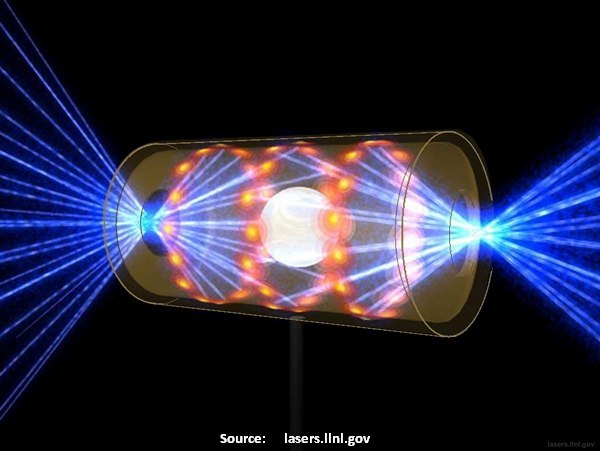
Fig 2 NIF 192 beams onto inner wall for x-rays that drives capsule implosion
- Laser light enters through holes in the ends of the shell.
- The 192 beams blast onto the chamber’s gold inner walls and turns the surfaces into plasma. The plasma generates an intense flux of x-rays.
- X-ray power impacts the target surface, driving an implosion into a fusing core.
The drawing hides reality. This diagram simplifies the real geometry; simplifies items that could generate issues.
- Thin beams shown as almost microscopically thin needles, striking the walls with surgical accuracy.
- Beam cross in a tight region just before the entrance holes. The beams never interact with each other.
- Edges of the entrance holes are never touched by the needle beams. Edges are never touched, never generate an interacting plasma.
- Beam needles are never close the target shell, never brush against it and prematurely start ionizaton.
- Beam strike points (red) on wall are uniformly distributed about the chamber ID. Where are diagnostic holes that allow researches to understand the shot?
The next diagram is a better representation of what actually happens.

Fig 3 A more realistic view of hohlraum geometry
Fig 3 is shows the beams are overlapping cones of light, the hohlraum shows overlapping strike bands. Now we can spot potential issue points.
- Inner beam enter near the central axis and reach inwards beyond the capsule.
- Outer beams enter at the steepest angle, strike closest to the ends
- Capsule fill tube (shown) keeps fuel inside the capsule prior to the shot. A major asymmetry?
- Chamber fill tube (not shown) maintains the hohlraum pressure at a desired level. Maybe an asymmetry, but it is the source of gas fill that we talk about later.
- Diagnostic windows (maybe shown), although present, do not appear to interfere with the beams that generate x-rays.
We still have the beams having ultra sharp edges and miss the target completely, though they are shown be very close. And they still seem completely unbothered by the end entrance holes and the equator’s diagnostic windows. But is this what happens?
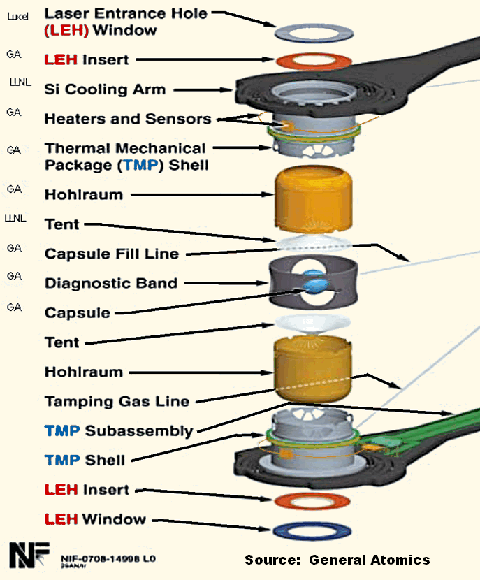
Fig 4 How a hohlraum is assembled.
Fig 4 is the final comment on hohlraum structure. This is from a GA capability brochure and shows the parts of a 1 cm long hohlraum.
This shows the diagnostic ports around the target equator better than anything else. (Return)
Problems with the design
We pointed out previously that their shots are strongly asymmetrical. NIF could be used to make a nifty plasma donut (and no refined sugar, either).
NIF Notes-Shells is the first evidence I have seen that the NIF system can make a central hot core. The lead author of the report, T. Ma, reported that the team used thinner than normal targets and short pulses with a fast adiabatic ramp up of intensity. Success.
However, there may be more to obtaining fusion than success with thin shelled targets. The NIF team usually reports beam total energy on target which is not an indicator of success. Instead, watch the energy per picosecond (power) arriving at the target.
The glass in the beamlines will disassemble (bust up, get damaged) if the intensity is too high. So there must be a limit to the allowed beam power.
To get the NIF-designed total energy, it may be that they need at least 20 nanoseconds of pulse. Catch 22? If they have the long pulse lengths will they obtain poor performance? But if with short pulses, do they get better results, but with insufficient power to push to designed compression? Again, this is just LastTechAge opinion. It looks like they are searching for a way to get quality implosion results without full facility energy.
Summary this section: The known but unexpalined loss in beam effectiveness may be due to NIF leaders believing their own PR hype – (Return)
- hohlraum geometry in PR – have large end holes with big holes at equator.
- beam structure in PR says sharp needles – have broad cones, fuzzy edges
- cross talk between beams and plasma not in PR – have a host of related issues
- cross talk between the beams are not in PR – have been used with tiny success.
New Hohlraum design
The media coverage over rugby hohlraums was generated by a NIF media release from a short publication by the theory modeling team. Aside from the confusing picture that LLNL provided, it left more to imagination than understanding.

Fig 5 Mordecai Rosen, Chief Scientist, AX Div, LLNL
LastTechAge comments follow directions pointed to by Dr. Mordecai Rosen’s October 2014 review paper, presented at the American Physical Society / Division of Plasma Physics general meeting.
He discussed what was going wrong rather directly, and what they were testing to correct it – possible paths to actual success.
Good lecture, good outline, good investigative strategy.
Geometry If you look back to Fig 1, you will see that both the standard cylinder and the new prolate (sausage-like) “rugby” designs have a main axis along the direction of elongation.
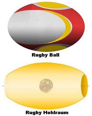
FIg 6 Why Rugby?
First – why call it rugby? In case you have not figured it out, Fig 6 shows the reason.
The new rugby is fatter – slightly wider– and a bit longer than the standard shape. The laser entrance holes at the ends are about the same size.
Am I the only one who thinks the design looks more like an American gridiron football? Probably because when I went to primary school, no school had a rugby team. But we did play football. (Return)
Cylinders are too small
Short summary – the walls of the standard cylinder are too close to the target.
When the laser beams strike the hohlraum wall, the generated plasma will blast into this open region and laser-plasma effects will mess up the illumination that drives the implosion. A second level effect is that the beam power extends beyond the nominal diameter and the its brush with the target shell could mess up any hope for uniform implosion. (I have not seen any discussion of possible beam preheat.)
They tried wider diameter cylinders. They built special test holhraums that were 6.72 mm in diameter, fatter than the standard 5.75 mm. Got much better results than from standard ones. To American readers: the difference is about 22% larger than 1/32-nd of an inch, so the space between the target and the chamber increased by a bit more than 1/64-th of an inch. Such a small change, such a spectacular result!
Wider cylinders gave them more time. The wider cylinders allowed more nanoseconds to elapse before wall plasma drifts into the region where it can interfere with the laser beams.
Standard practice, Gas-Fill – fill the hohlraum with gas at nearly atmospheric pressure. Zeroth order effects: wall plasma expansion is slowed down. 1st order: beam-plasma “SRS” interactions keep high quality compressions from happening.
The added time let them run shorter pulse lengths at reduced gas fill. It is unclear from comments whether they tested vacuum hohlraums.
Pulling the walls further from the target reduces SRS! Who’da thought? Not LLNL top management! They ignored old NOVA data showing these exact degradations (the link is to 1998 report but the data is from very much earlier Classified days with the NOVA laser). The NIF team is only now now being allowed to investigate SRS effects – 25 years after start of construction and 6 years after start of operations.
(Free Tip : keep the fusion region as far from the walls as possible ⇐ this is why the ITER tokamak is huge.)
Data from Rugby shots is superior. We will discuss this more, below. Rosen says that rugby hohlraums were under consideration last year. I suspect that they are now regularly running rugby shots, in between their primary weapons studies work.
Here is a older report on shots taken at the Omega laser ( LLE, Uni Rochester). The team included people from LLE, NIF and the French LMJ (Laser MégaJoule) facility, currently coming on line. It was submitted in 2009 from data taken, probably in 2007 or 2008. There are more recent data from NIF shots, too.
BTW The French LMJ started up 12 years after they started digging the new building. It sounds as though ICF/IFE tests will start with rugbys. NIF is in danger of being eclipsed by the French! Aw, Ed Moses, say it ain’t so! (Return)
Shape details

Fig 7 Geometry comparisons, cylinder vs rugby, using LLNL dimensions
Fig 7 shows our drawing of the overlay of a standard cylinder on a rugby shape. These are the sizes in Rosen’s 2014 report. The target image is scaled to its standard 2.2 mm size.
Representative beam rays are shown on the right in blue. These are meant to approximate a median path for the beams as drawn in Fig 3. The wall hit points are about where they are shown in that figure, also. It is the inner beam strike points that are pulled away most from the target.
Half of the beams enter from the right and strike the wall symmetrically about the central axis. The other half enter from the left, and the central emission is from the overlap of the two sets of inner beams.
Most reports on actual rugby tests state that a symmetric stagnation kernel is much easier to generate in rugby forms than in cylinder forms.
Another small observation – in the rugby form, the hit points are curved toward the target. Since maximum x-ray intensity occurs perpendicular to the surface, the curved emitting surfaces will direct (“focus”) the highest intensity onto the target shell. Does the rugby target intercept higher fraction of x-rays? (Return))
Physics Details
 Count the modes. NIF entered its Oopsie time just after the first core shapes came from the diagnostics.
The implosion stagnation core at Bang Time should be a completely spherical ball. Many such spherical implosions have been achieved, over the past decades.
The shape can be described by “Legendre” mode numbers. A Legendre mode m = 0 is a sphere, a ball that is symmetric in all directions. But NIF shots have not been symmetric.
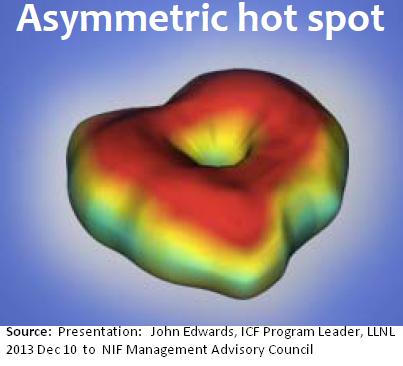
Fig 8 NIF stagnation core
The cylinder-shot shown in Fig 8 is dominated by 2 lobes so m = 2. Wonder if the lobes are related to the two diagnostic holes in the hohlraum?
Mode numbers of 4 and 6 are reported worries. The higher the mode number, the more the core is divided into separated kernels, each trying to do its own fusion thing. If they had gotten m=0 and collapse to a single kernel, they would have had chances of significant self heating from fusion alphas.
Don’t worry about why Monsieur Legendre from 1800 has his name on these things. The mode picture is easy to visualize but it refers to math, not appropriate for a blog! If you read Stambaugh’s comment, you know experimenters join bloggers in wanting to avoid math.
Cross-Beam Energy Transfer (CBET) They can shift power from the inner beamlines to the outer ones or vice verse, by shifting one set of wavelengths slightly (usually reported as “Δλ”. Details are not important here. This is an attempt to correct the shape imbalance, to have a chance at m=0.
The zeroth order approximation shows this works fine, first order corrections to the idea say that the beam power shifts during a pulse; power changes during the shot. CBET cannot work perfectly. Not the path to fusion salvation.
Laser-Plasma Interactions LPI (called parametric instabilities) are the most math-dependent of ICF issues, because they describe effects of a light wave’s oscillating electric field on a plasma as it passes through.
Plasma waves are generated by the beam. They not only sap energy from the beam, but can cause the light, itself, to scatter. Maybe hard to talk about, but they are the basic reasons why laser fusion power plants are not on line today.
Two important LPI effects: SBS (stimulated Brillouin scattering) and SRS (stimulated Raman scattering), there are others. I ap0logize to all who think my descriptions are too simplified
-

Fig 9 SBS causes back reflection
SBS When lasers pass through low density plasmas, they generate plasma sound waves (ion-acoustic waves) and are backscattered. Energy is lost to the plasma but portions of the beam will also scatter backwards along the laser path.
SBS can and has done significant damage to the optics of any test facility. Fig 9 shows the process for a direct drive test where lasers try to compress the target.
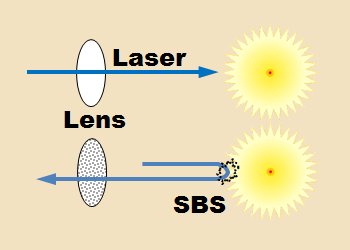
It’s pesky for direct drive but NIF uses x-rays on its targets. At NIF, SBS annoys by passing through the ionized prefill gas and the wall plasma when it moves into range. The CBET does use a form of SBS to exchange energy between the outer and inner beams, but really, you do not want SBS around.
-

Fig 10 SRS causes preheat
SRS When the laser beam passes through a plasma the plasma electrons with the highest velocity will be accelerated to extremely high energies by the SRS. The longer the wavelength for the light beam, the slower original electrons can be and still be caught up by SRS. Fig 10 shows the process.
These ultra hot electrons will flow freely into the collapsing fuel and preheat it prior to stagnation (Bang Time). With preheat, there is too much thermal back-pressure and the core will not develop the expected high density. pfffft … no fusion. As simple as that, and nasty to have around. The original IR lasers had huge SRS emissions and almost ended the ICF dream then and there.
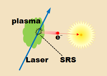
The gas-fill method of stopping wall plasma will always generate SRS. Gas fill is always used, gas fill always ionizes to plasma, SRS always preheats, implosion results always fall below modeling code expectation. NIF’ers sad …Arrgh. (Return)
New Hohlraum Shape
It has been a long path to get here, to our conclusion. The prolate rugby shape should be tested to the utmost. I would suggest an even more oblate (fat) form with the walls further away and curving even more toward the target.
Too bad x-rays do not reflect. Otherwise, maybe I would propose a DBIS type hohlraum for symmetrical implosions.
……………………………….
Charles J. Armentrout, Ann Arbor
2015 Jun 14
This is listed under Technology, in thread Fusion-ICF/IFE
Have a comment? Click on the title of this post, go to bottom, let us know.
Related posts: Click the INDEX button under the Banner picture

“Why call it Rugby ?” : the answer is because the first design of such an holhraum is French.
See
Prolate-Spheroid (“Rugby-Shaped”) Hohlraum for Inertial Confinement Fusion
M. Vandenboomgaerde, J. Bastian, A. Casner, D. Galmiche, J.-P. Jadaud, S. Laffite, S. Liberatore, G. Malinie, and F. Philippe
Phys. Rev. Lett. 99, 065004 (2007)
and References within.
LikeLike
Thanks for the reference, I was aware of the significant influence that the French scientists have at Omega and NIF. The French ICF presence was solid and innovative decades ago when I was involved. I am not at all surprised that the French freedom to pursue for new ideas pays off with excellent results.
LikeLike