NIF reports tests with capsule designs that illuminate the path toward great results
During the early spring (2015), the National Ignition Facility (NIF) at LLNL released/published several modifications to the targets worth discussing.
- One is the realization that the gossamer tents used to hold the spherical targets in place actually cause detrimental asymmetry in the resulting implosions. Report
- One is the demonstration that thinner ablative shells around the targets implode faster, with better spherical symmetry and with no shell mixing into the fuel that that might poison ignition. ← most exciting of the three.
- One was the future shift to a new hohlraum chamber shape, changing the current (nearly) open cylinder to an egg shaped one with holes in the two ends. Report
These are all good steps forward; here we discuss the Second point, on target shell thickness. A test of the survivability of a thin walled capsule is important because of worries that if the wall is too thin, it will break up during the implosion and poison the resulting core.

FIg 1 Tammy Ma, NIF Scientist
We are discussing the April 2015 published paper with Dr. Tammy Ma as its lead author.
As with most facility physics work, 74 authors are listed, including Drs. Hurricane and Edwards. Many of these 74 were not involved in writing the paper, but were deeply involved in capsule issues, diagnostic operations and analysis, computational analysis, and other such activities very necessary for success.
The investigators fired NIF beams with the same power level into 3 different targets with different ablative shell thicknesses. Only one “popular press” source, phys.org, has taken notice of these data.
So, though not much other notice has been made, these results are extremely important. Here’s hoping that NIF leadership pays attention!
Structure of a Target Capsule
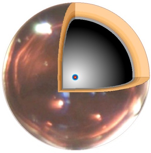
Fig 2 Target capsule cutaway. Compressed core is shown at the center (red)
Fig 1 is the cut-away drawing a NIF target (called the capsule). The basic image is of sphere is of 2.2 mm diameter, from the LLNL image library. Our earlier capsule description in a different post.
The capsule has on the outside, an ablative shell composed of 5 layers of plastic (formvar), with small additives for diagnostic purposes.
On the shell’s inner surface is a layer of DT ice, the fuel to be compressed. All three targets had 5 micron penetrating holes drilled used to introduce the DT into the shell. The central void is DT vapor.
Report Data
Fig 3 is from an earlier NIF report and shows an x-ray image of a cryogenic target, that is one that has the DT frozen to an ice layer. The specifications in the text below the image are our scaling of the picture to the specified 68 micron ice thickness (2.7 thousands of an inch). Dr. Ma’s paper says that the target OD is 2.2 mm and the cryo layer is 69 µm thick.
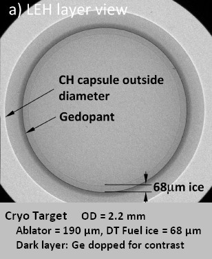
Fig 3 X-ray Image of a cryo capsule
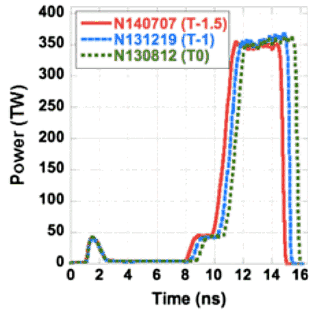
Fig 4 Pulse shapes for Shell thickness study
Fig 4 shows the NIF laser pulse shape for the test shots. (For reference, 1 ns means 1 billionth of a second.)
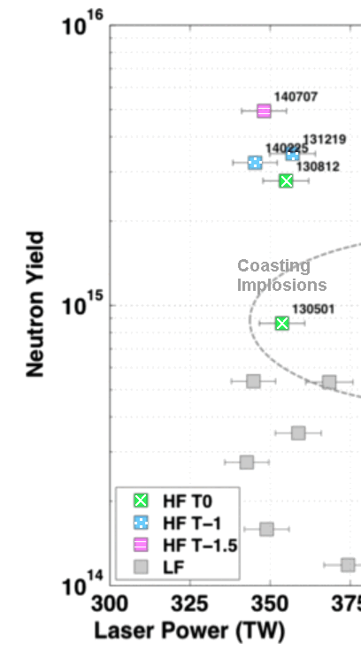
Fig 5 Neutron yield for the capsules

Fig 6 Images at stagnation. 2 x-ray views, 1 neutron (red, primary emission; blue downscattered haze)
Fig 5 shows neutron emission data.
- N130812 is labeled “T0” the standard shell thickness of 195 microns.
Fig 5: green+X - N131219 is labeled “T1” with shell of 175 µm, 10% thinner than T0.
Fig 5: blue+dots - N140707 is labeled “T1.5” with shell of 165 µm, 15% smaller than T0.
Fig 5: red+stripes
Fig 6 show images for the fully imploded cores. “Equator” means side view and “Polar” means top view. Neutron imaging has less resolution than x-ray emission imaging so the images appear simpler.
LF shots are the gray point in Fig 5. These are very long pulses, the type we complained about when discussing the RT universal instabilities. They have generate unusable stagnation cores, have thicker shells and display the signatures of shell breakup and mixing in the data analysis. LF shots lie on the “bad” end of every analyzed data summary.
Both Figs 5 and 6 have been trimmed from data in the article. None of the data points have been modified but there is additional data that is not directly comparable and has been trimmed out. For example,
(A) The basic T0 capsule shows NIF’s standard donut shape of earlier presentations. This explains the poor performance on the neutron yield plot.
- The 10% thinner T1 capsule is an intact core(!) but elongated, with 2 fusing centers.
- The 15% thinner T1.5 core is the first image we have seen of a compact single knot core from NIF. Fusion production is clearly higher than any from the thicker targets.
(B) Analysis shows that at least 50% of the neutron flux comes from fusion caused by alpha products from fusion events. … a must-have if the core is to sustain fusion.
What it means
Shorter Pulses First note that these shots are all shorter than 15 ns, not 20 ns as in our “NIF shifts to…” series of discussions. Even better, the HF shots here all have the large main pulse lasting about 5 ns total. They got better results, too.
A next step would be ramp the pulse intensity, from low to highest at when the stagnated kernel is finally assembling. This is the adiabatic drive discussed earlier. We (KMSf) tested NIF’s current picket fence strategy (initial pulses to start inwards drift) and they did not work as well..
Thinner Shells Result (A) indicates that the thinner on the capsule, the more efficient the setup is to generate power. One of the big worries has been the question of whether the ablation shell would break up, mix with the fuel and drain power needed to heated the core. If it happened you would never build a power plant. As Dr. Ma said, the thinner shell lets the target implode much faster. The inwards acceleration changes from monstrously high to unimaginably huge.
Thinner is better – good-news results. The next step should be to test ever thinner shells until they experience breakup. Where is the “sweet spot” for shell thickness?
Alpha Heating Result (B) indicates that 1/2 the total power produced was from alpha heating. Although these are not new results, NIF’s reported high alpha self-heating is another sign that thin shell strategy is an effective move toward ignited cores.

Fig 7 DT fusion results in 1 alpha and 1 neutron
Ignition The DT fusion reaction is shown in Fig 7. The alpha and neutron fusion products carry the energy of the reaction.
To make power production economical, alphas must collide (slow down) in the core, heat it and cause additional fusion events. You must not loose this energy from the fusing core.
Ignition is what we call core heating from fusion generated alphas; it is required for net power production. Ignition is the goal the world-wide fusion community has long worked to achieve. And NIF appears to be on the path to an ignited plasma.
Good results, the best of the three Spring-2015 trends we are discussing.
……………………………….
Charles J. Armentrout, Ann Arbor
2015 May 31
This is listed under Technology, in thread Fusion-ICF/IFE
Have a comment? Click on the title of this post, go to bottom, let us know.
Related posts: Click the INDEX button under the Banner picture
